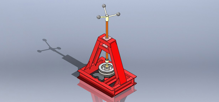
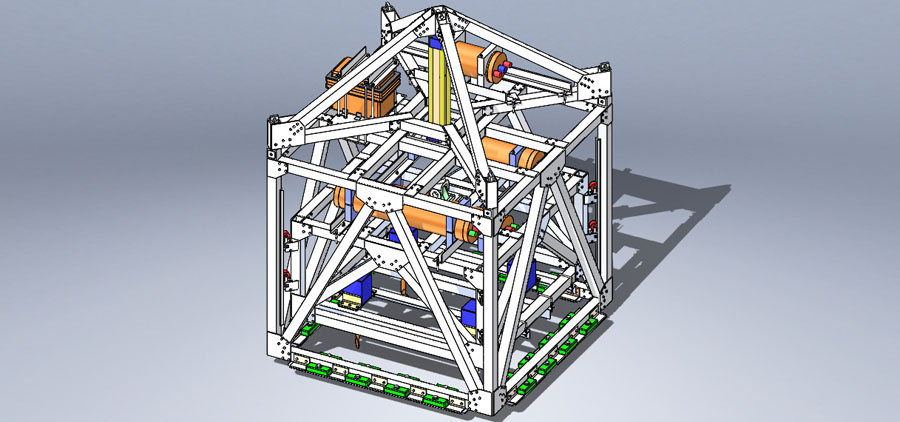
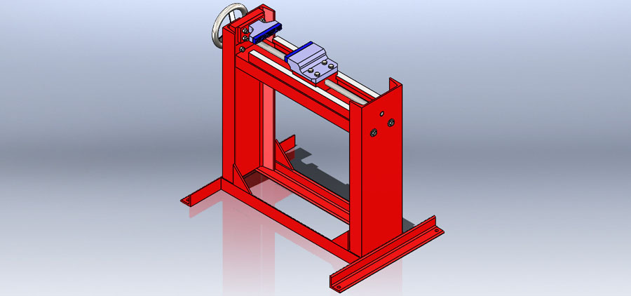
Floor Vise and Assembly Drawing
The Floor Vise is an example of the mechanical equipment designed at DESE. The CAD drawings needed to build
this Floor Vise can be seen by clicking on the SolidWorks icon to the right. The video below shows the basic
operation of the Floor Vise.
SolidWorks CAD Drawings.
SolidWorks is used for all of our
CAD work. All that is required
from you is a rough sketch of
the product that you need. From
this, we can provide you with
CAD drawings and a 3D model
of your product.
CLICK ON THE SOLIDWORKS
ICON BELOW TO SEE THE FLOOR
VISE'S DETAIL AND ASSEMBLY
DRAWINGS.
SolidWorks is also used to
create a Finite Element Stress
Analysis (FEA) of your design to
ensure structural integrity or
code compliance. Click on the
'PRIMARY SERVICES' link above,
and then the 'Finite Element
Analysis' icon to see FEA
analysis examples.


Connect With Us