-
Delta Engineering SE
Mechanical and Ocean Solutions
FEA (Finite Element Analysis) Using SolidWorks Simulation
FEA is used to ensure that structural and mechanical products will support their design
loads. Classical stress analysis (CSA) is used on common structural components when
mechanical properties are known. FEA is used on uncommon shapes whose mechanical
properties are not known, or for structures that are too complex for CSA. When running an
FEA analysis, a SolidWorks model of the product is constructed. This model is imported into
SolidWorks Simulation, where material properties, boundary conditions and loads are
applied. After the FEA analysis has been run, stress and deflection plots, like the examples
shown below, are generated. The stress values in these plots are compared to the product's
material yield strength to ensure he product's structural integrity.
The slide show below shows the FEA results of mechanical and structural components when subjected to their
respective design loads.
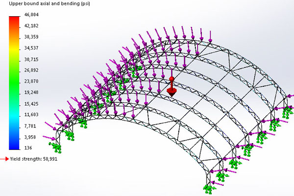
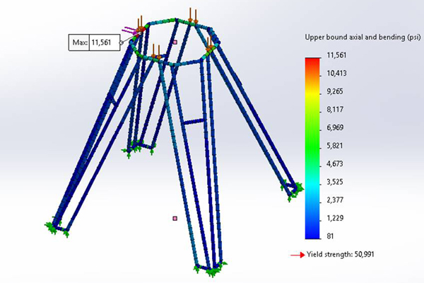
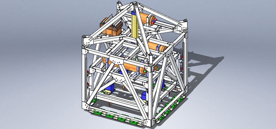
Tent Support Structure Stress, Load = 100 mph (161km/hr) Wind.
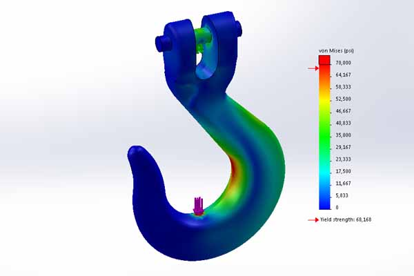
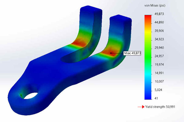
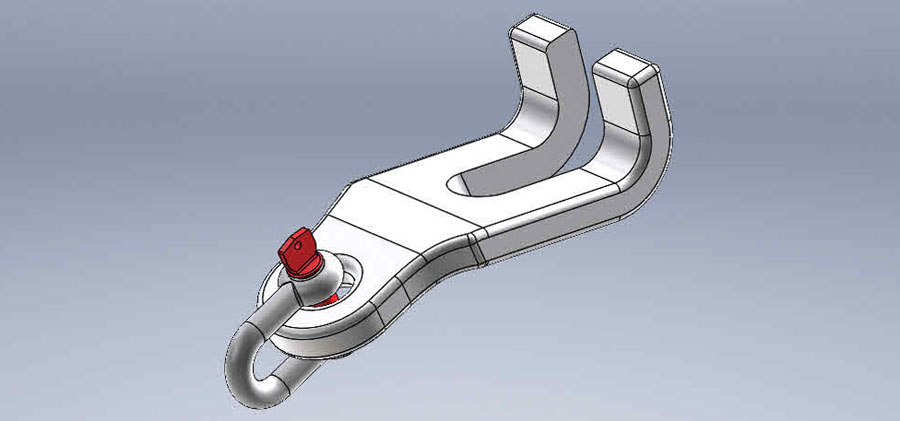
Chain Hook Stress, Load = 5 kips (22.2 kN).
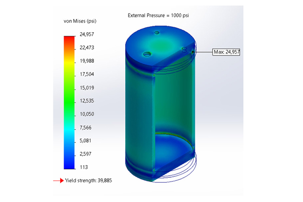
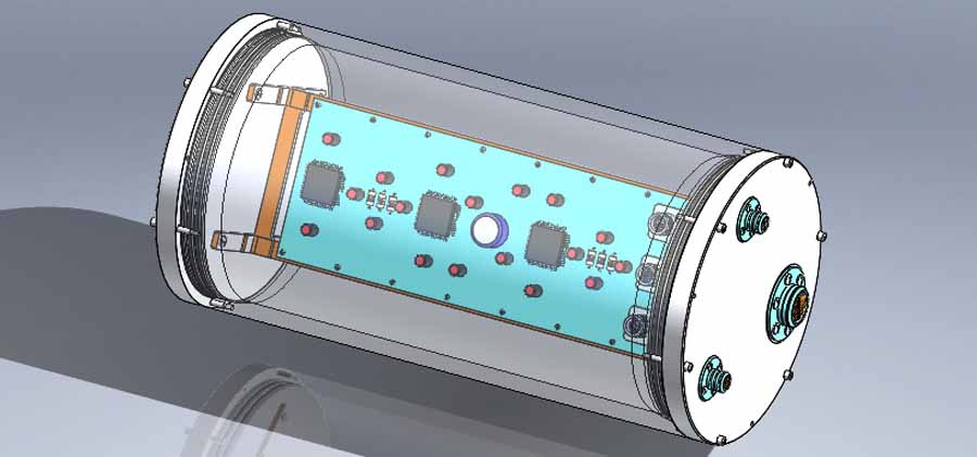
IPV Stress, External Pressure = 1000 psi (6.9 MPa).
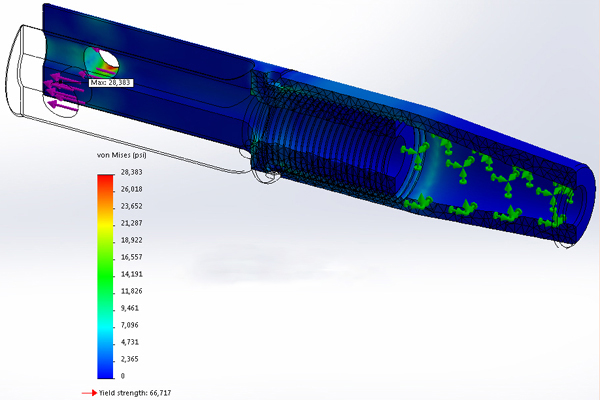
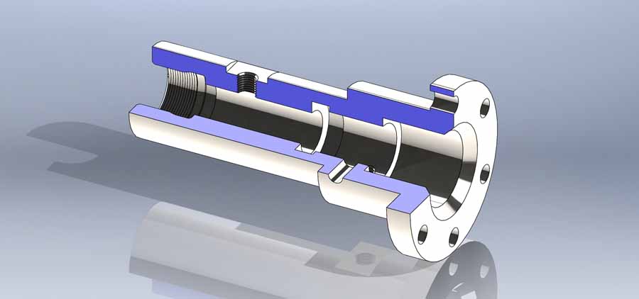
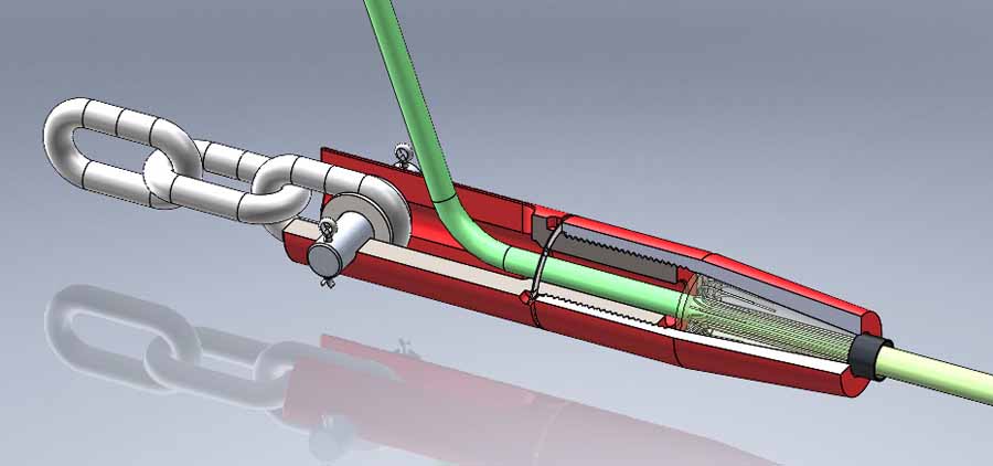
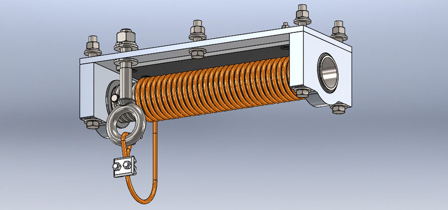
Armored Cable Termination Stress, Load = 10 kips (44.5 kN).
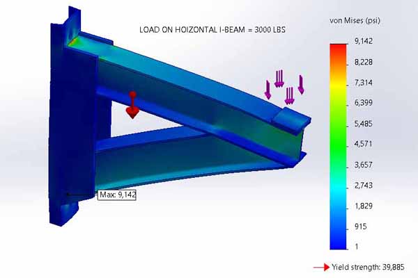
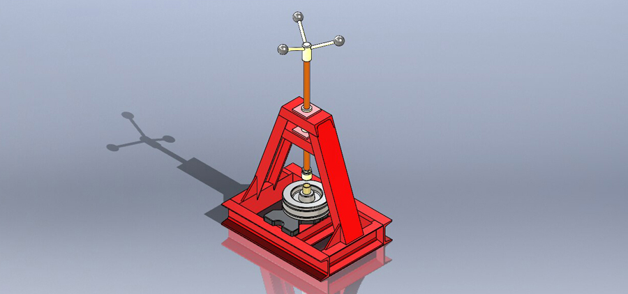
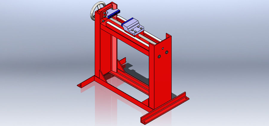
Boat Lift Piling Support Stress, Load = 3 kips (13.3 kN).
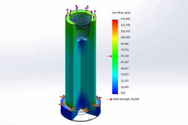
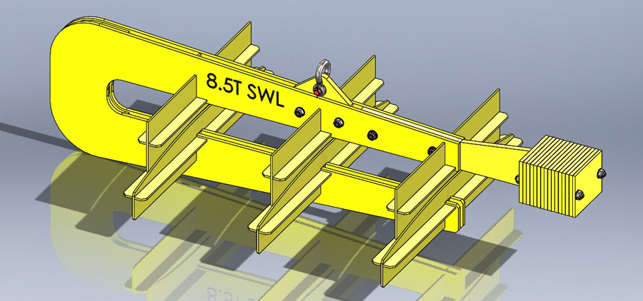
BLAT Drive Pipe Stress, Load = 2000 kips (8.9 MN).
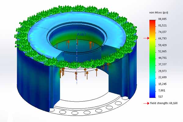
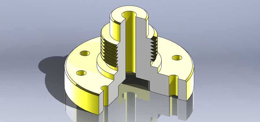
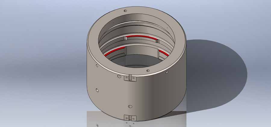
BLAT Top Breech Lock Stress, Load = 2000 kips (8.9 MN) .
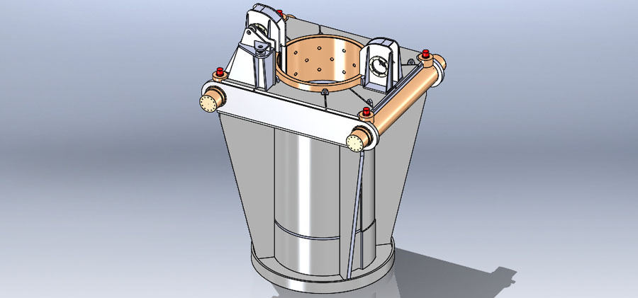
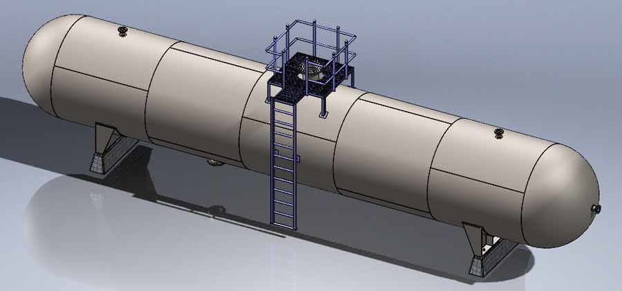
Storage Tank Weldment Stress, Load = 24 kips (106.8 kN) .
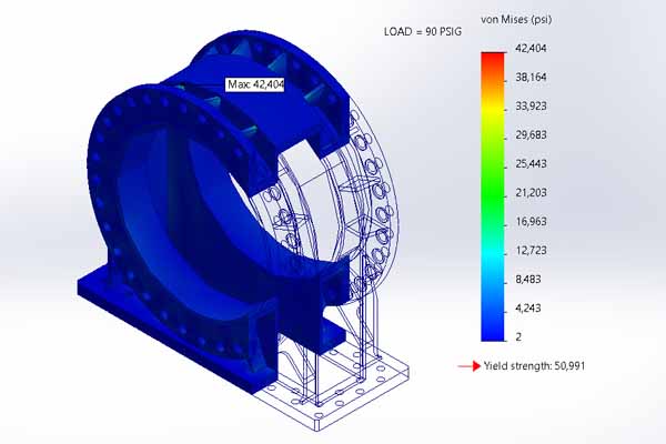
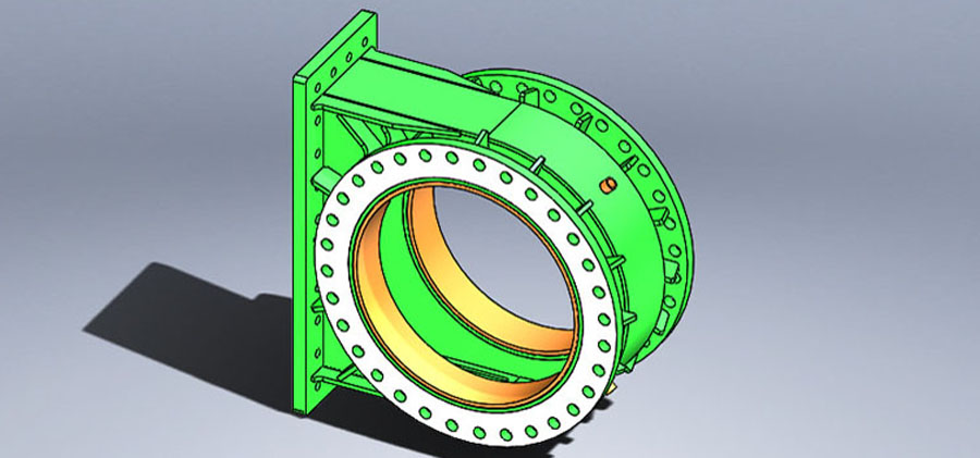
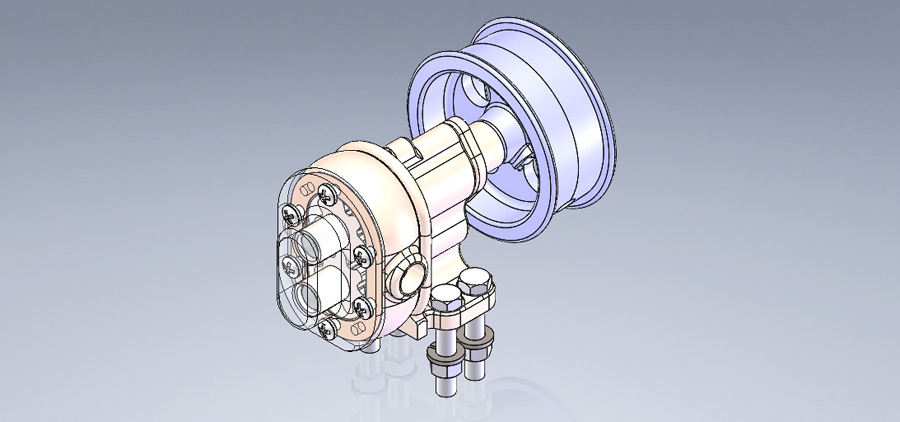
Slurry Gate Valve Stress, Load = 90 psi (620.5 kPa) .
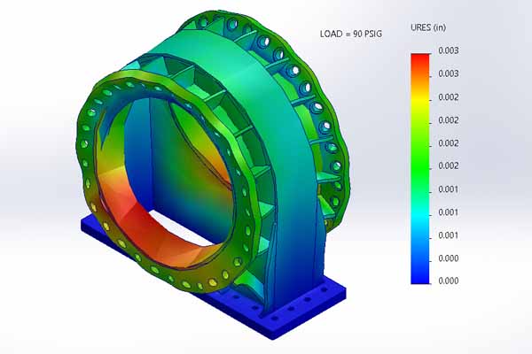
Slurry Gate Valve Deflection, Load = 90 psi (620.5 kPa) .
Anchor Chain Hook Stress, Load = 12 kips (53.37 kN) .
What FEA Can Do For You
FEA is used to calculate
stress and deflection in
mechanical and structural
assemblies which are
subjected to their design
loads & whose complex
geometries don't allow
the use of CSA.
SolidWorks Simulation
uses FEA to improve a
product's reliability by
predicting its behavior
when subjected to it's
design loads.
CLASSIC BEAM STRESS ANALYSIS EXAMPLE
Click on the STRESS
FAILURE CRITERIA ICON
below to see a MapleSoft
Mathematics Software
stress analysis that
calculates stress &
deflection in I-Beams
when they are subjected
to their maximum design
load.


Connect With Us